One board for everything
At the end of the last part I had a three-board stack: counting and scrolling on the bottom, VRAM and the GPU interface in the middle, and Ben's 6502 computer on top. It worked, but the GPU was hard wired to the 65c22, so there was no room to plug anything else into the computer.
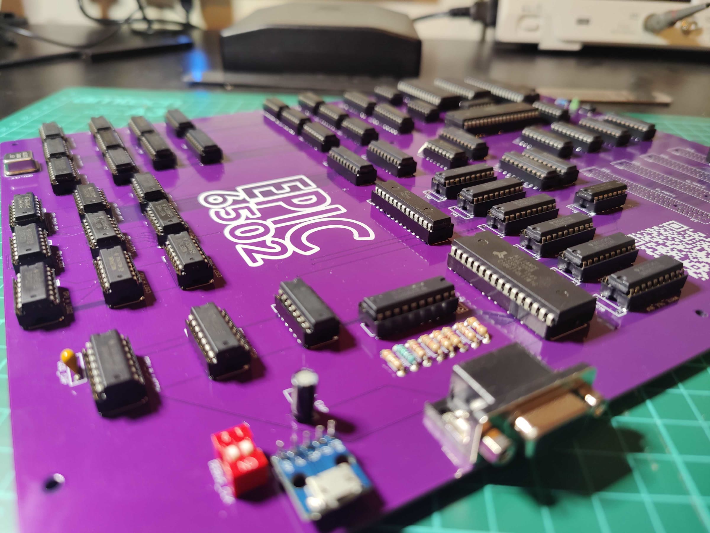
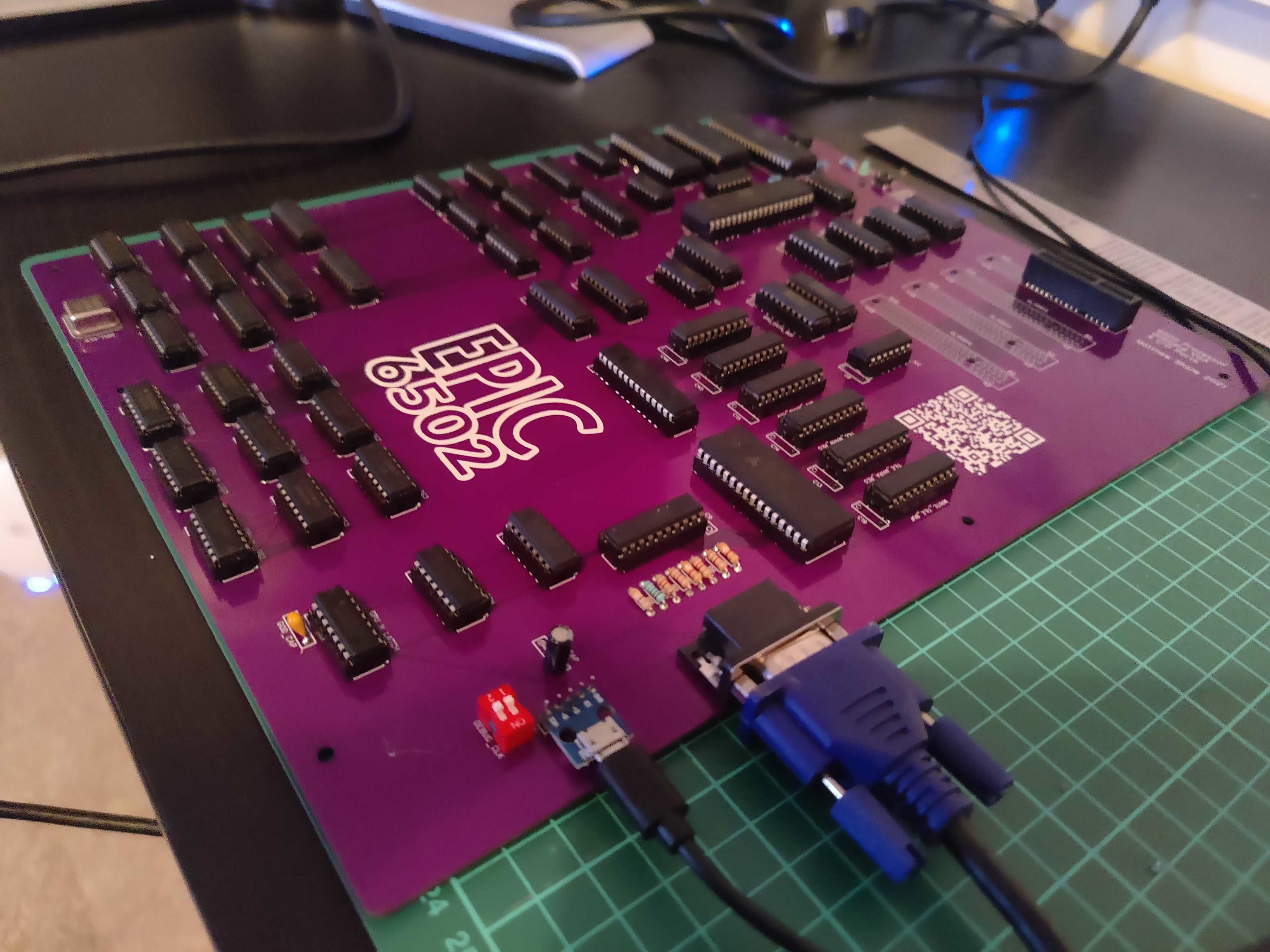
Rather than add more layers to the stack, I put everything onto a single board: the computer, the whole GPU, and four expansion ports. It's massive. I called it the EPIC 6502.
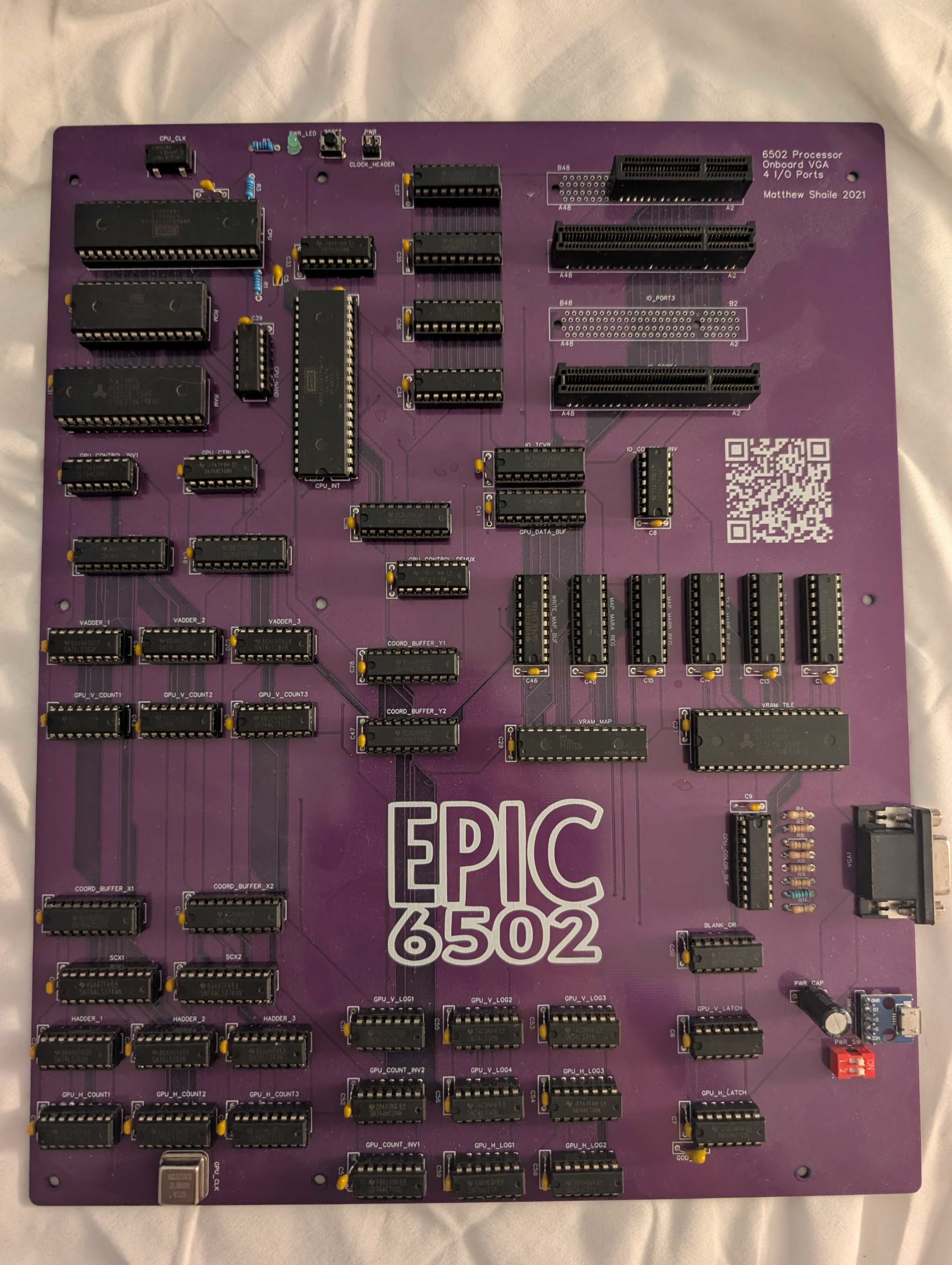
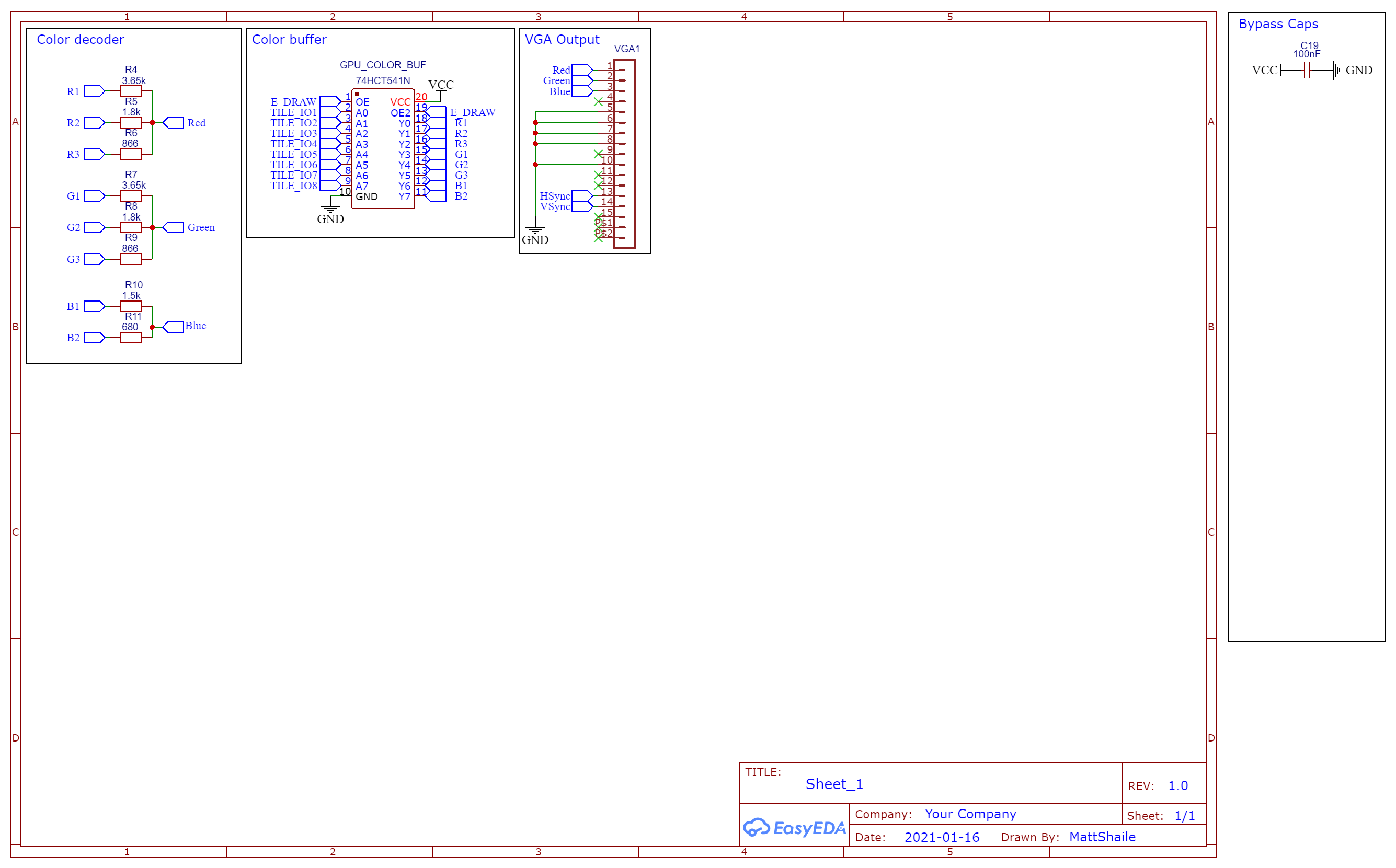
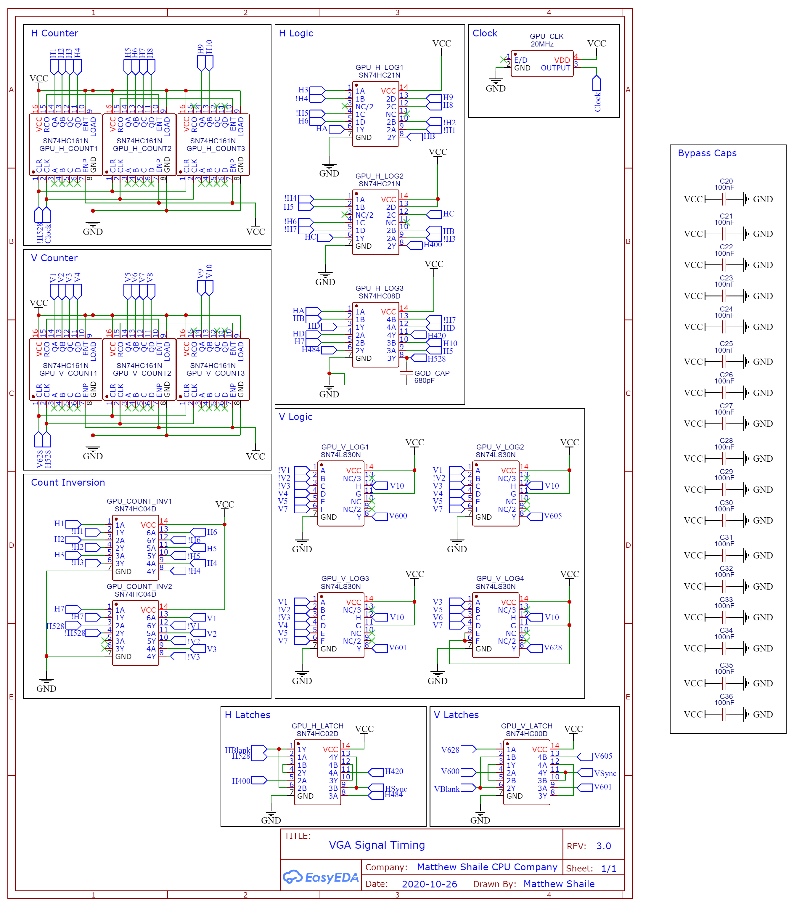
Everything from the previous parts is on there: the counters and sync logic, the scroll registers and adders, the tile and map VRAM, the colour output and VGA connector, and the 65c02, 65c22, RAM and ROM. Power comes in through a little USB breakout board, and the four I/O ports run along the top edge.
The final specs
The computer:
- 65c02 CPU at 1Mhz
- 16kb RAM
- 32kb ROM, holding the BIOS and BASIC
- 65c22 VIA, with a timer interrupt every 50ms
- 4 I/O ports, each with an enable line, a bi-directional 8-bit data bus and 4 control lines
- Clock bypass header, for debugging with a custom clock
The GPU is the same as in part 3:
- Screen resolution: 400x300
- Colours: 256 (RRRGGGBB)
- Tile memory: 256 tiles, 16x16 pixels per tile
- Map memory: 256x128 tiles (4096x2048 total pixels)
- Hardware scrolling
- Clock frequency: 20Mhz
- VGA mode: 800x600 @60hz
And the memory map:
$0000 - $3FFFRAM ($0100 - $01FFis the stack)$4000 - $5FFFunused$6000 - $600Fthe 65c22 VIA (mirrored up to$7FFF)$8000 - $FFFFROM
Sharing the VIA
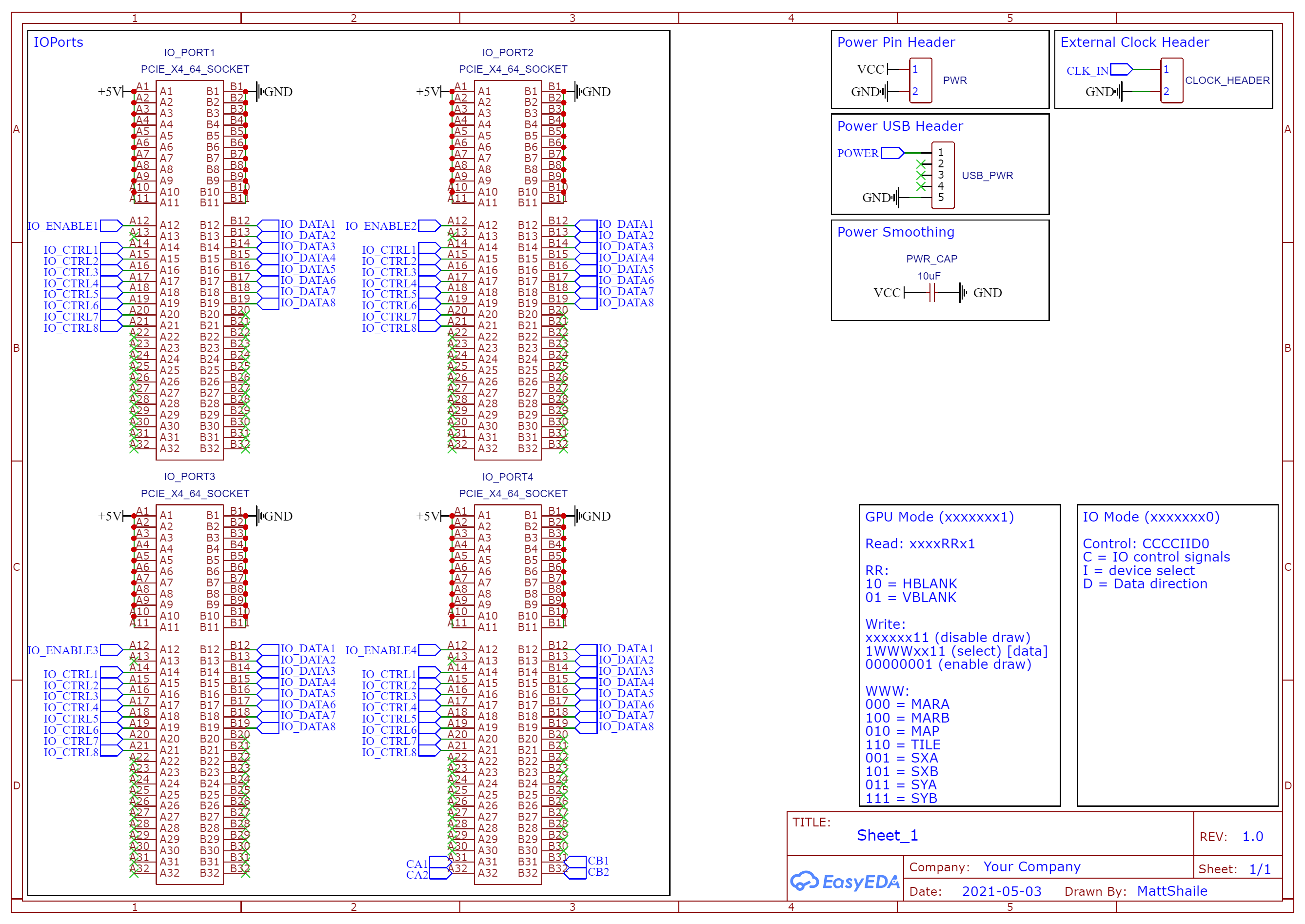
The GPU and the expansion ports share the VIA's two 8-bit ports: one carries data, the other carries control signals. The lowest bit of the control byte decides who's listening.
When it's 1, the byte is a GPU command, using the same protocol as part 3: select a register, write the data, then enable or disable drawing. When it's 0, the byte goes to the expansion ports instead: two bits pick one of the four ports, one bit sets the direction of the data bus, and four bits are control lines passed through to whatever card is plugged in.
So reading from an expansion card means switching the VIA's data port to input, sending a control byte addressed to that card, and reading the data port. The GPU's hblank and vblank signals stay readable on the control port the whole time, so programs can still wait for vblank before drawing.
Cartridges
The only expansion card I made was a cartridge: a small board with a ZIF socket holding a 2Mb flash ROM, so the chip can be swapped in and out easily. I could program a chip on my PC, drop it into the socket, and the computer would boot whatever was on it.
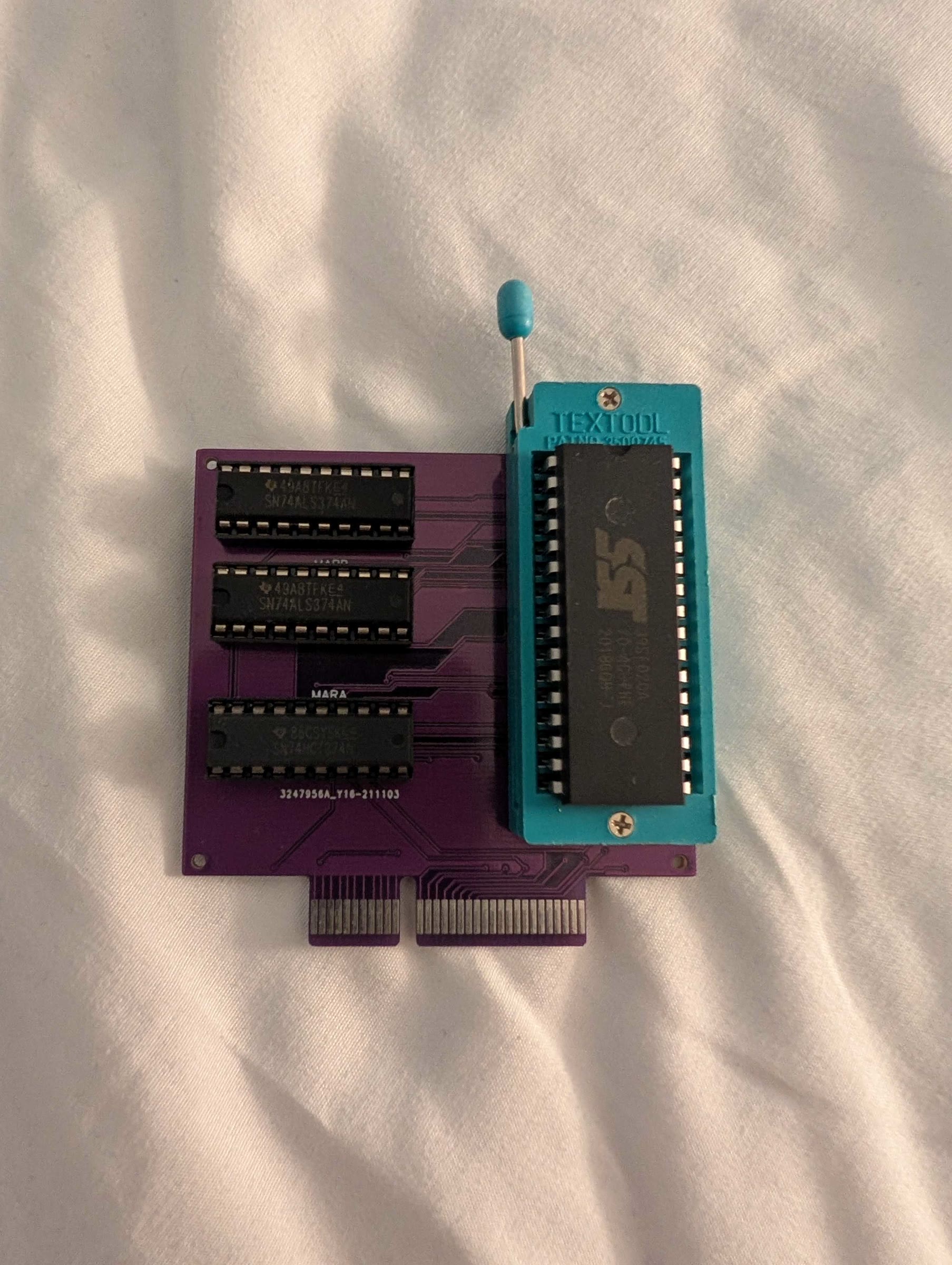
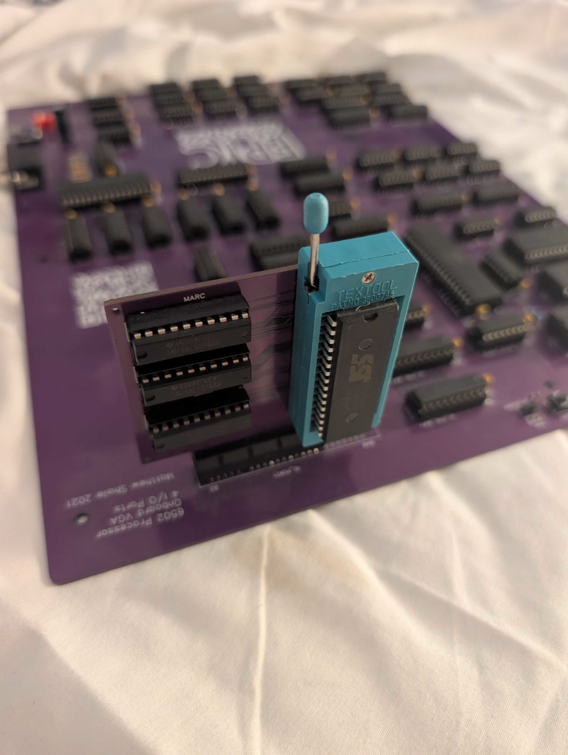
The other three chips on the card are 74ALS374 latches, labelled MARA, MARB and MARC. Each one holds one byte of the address being read.
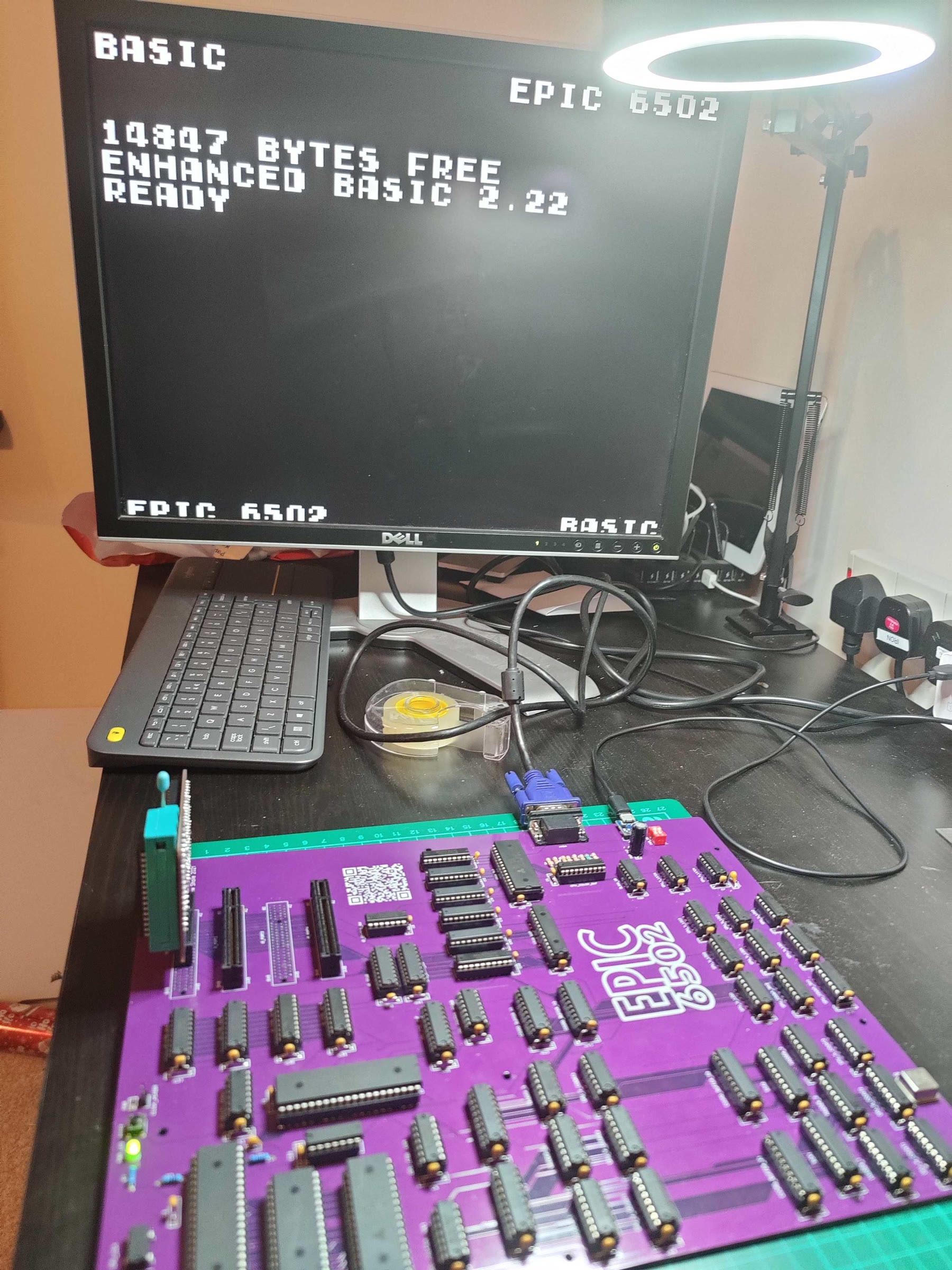
Here it is plugged into the board, sticking up on the left, with BASIC running on the monitor:
To read a byte from the cartridge, the computer writes the address to it as three bytes, then reads the data back. The 256kb of flash is split into 64kb pages:
- Page 0: the tile set, all 256 tiles at 16x16 pixels, one byte per pixel
- Page 1: the tile map
- Page 3: the program, plus a couple of header bytes: a load mode, and where the program ends
A cartridge carries its own graphics as well as its code, a bit like a games console cartridge.
Making a cartridge
The tile set is a 256x256 image (a 16x16 grid of 16x16 tiles) drawn in Photoshop in indexed colour, using a palette file that matches the GPU's 256 colours. Maps are made in Tiled, and programs are written in 6502 assembly and assembled with vasm. A Node script then packs the three into a single binary ready to flash onto the chip, plus a copy the emulator can load.
I made four example cartridges:
- Enhanced BASIC
- A Pokémon-style tile map which scrolls around the whole map
- A counter driven by the timer interrupt
- A test for a game controller card
The BIOS
The ROM holds a small BIOS. On reset it:
- Sets up the stack, the VIA and its timer, and resets the GPU's address and scroll registers
- Fills the screen with a solid black tile while everything loads
- Reads the cartridge's load mode
- Copies all 256 tiles from the cartridge into the GPU's tile memory
- Loads the map: either the whole thing, or in the faster mode just the 25x19 tiles that fit on screen
- Copies the program into RAM at
$0403and jumps to it
Every byte goes through the VIA one at a time on a 1Mhz CPU, so loading a cartridge isn't instant. That's why I added the faster load mode, and changed the program loader to only copy as much as the program actually needs rather than the whole page.
The emulator and the real hardware didn't always agree. A much faster routine for copying tiles into VRAM worked perfectly in the emulator, but needed changing before the real board would accept it.
Once a program is running, it can still call the BIOS routines for drawing tiles, scrolling and reading the cartridge. The BIOS also counts timer ticks and passes interrupts on to the program's own handler.
BASIC
The thing I was most pleased with was getting Lee Davison's Enhanced BASIC 2.22 running. BASIC itself lives in the ROM alongside the BIOS. The BASIC cartridge carries the font, with each character drawn as a tile, plus a tiny program that jumps into BASIC.
BASIC knows nothing about my GPU. It just calls an output routine with one character at a time. I wrote that routine to draw the character's tile into the map at the cursor position (the tile number is simply the character's ASCII code), and to handle backspace, carriage returns and line feeds. The screen is 25 tiles wide, and when the text reaches the bottom it wraps back round to the top. I started on using the hardware scroll registers to scroll the text instead, but never finished it.
Getting BASIC running was also a great test of my emulator. It flushed out a whole list of bugs in my 6502 emulation: missing opcodes, a broken indirect JMP, ADC and SBC not being quite right, and flags not being set on stack pulls. After fixing those, my commit message says it "seems to run BASIC flawlessly!"
The real board had no keyboard, so typing programs in only ever worked in the emulator, which pushes key presses straight into the memory that BASIC's input routine checks.
The emulator
All of this was developed against the browser-based emulator from last time, which grew into an emulation of the whole machine: the 65c02, the 65c22 and its timer interrupts, the GPU, and the cartridge. Building a BIOS or a cartridge would also mount it in the emulator, so I could test a program on my PC before flashing it onto a chip.
I also tried out a game controller card, but only in the emulator. The controller test cartridge reads buttons from I/O port 2, and the emulator maps them to keys on the PC keyboard. I never built the real card.
You can run the emulator, with the BIOS and example cartridges, right here in your browser.
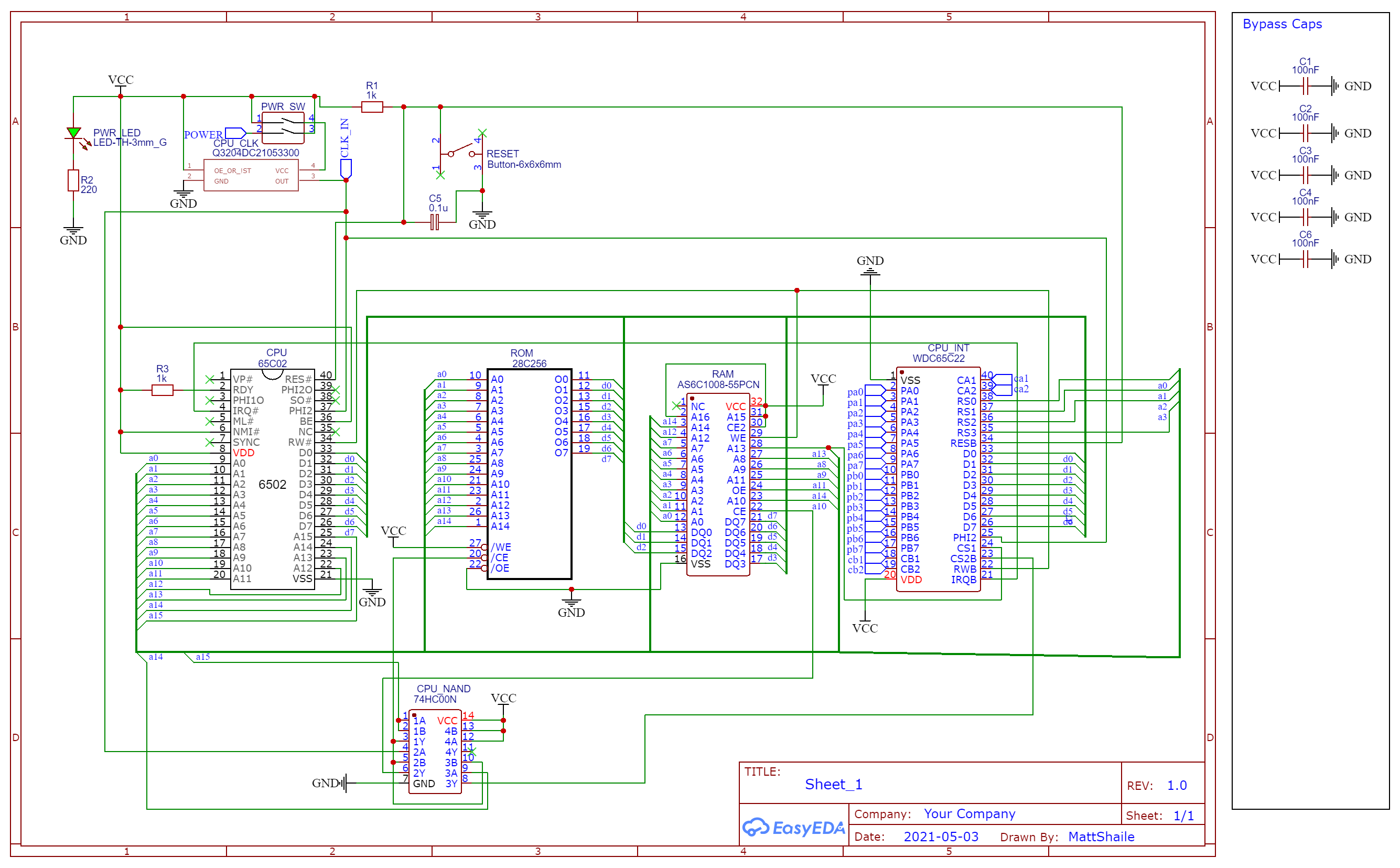
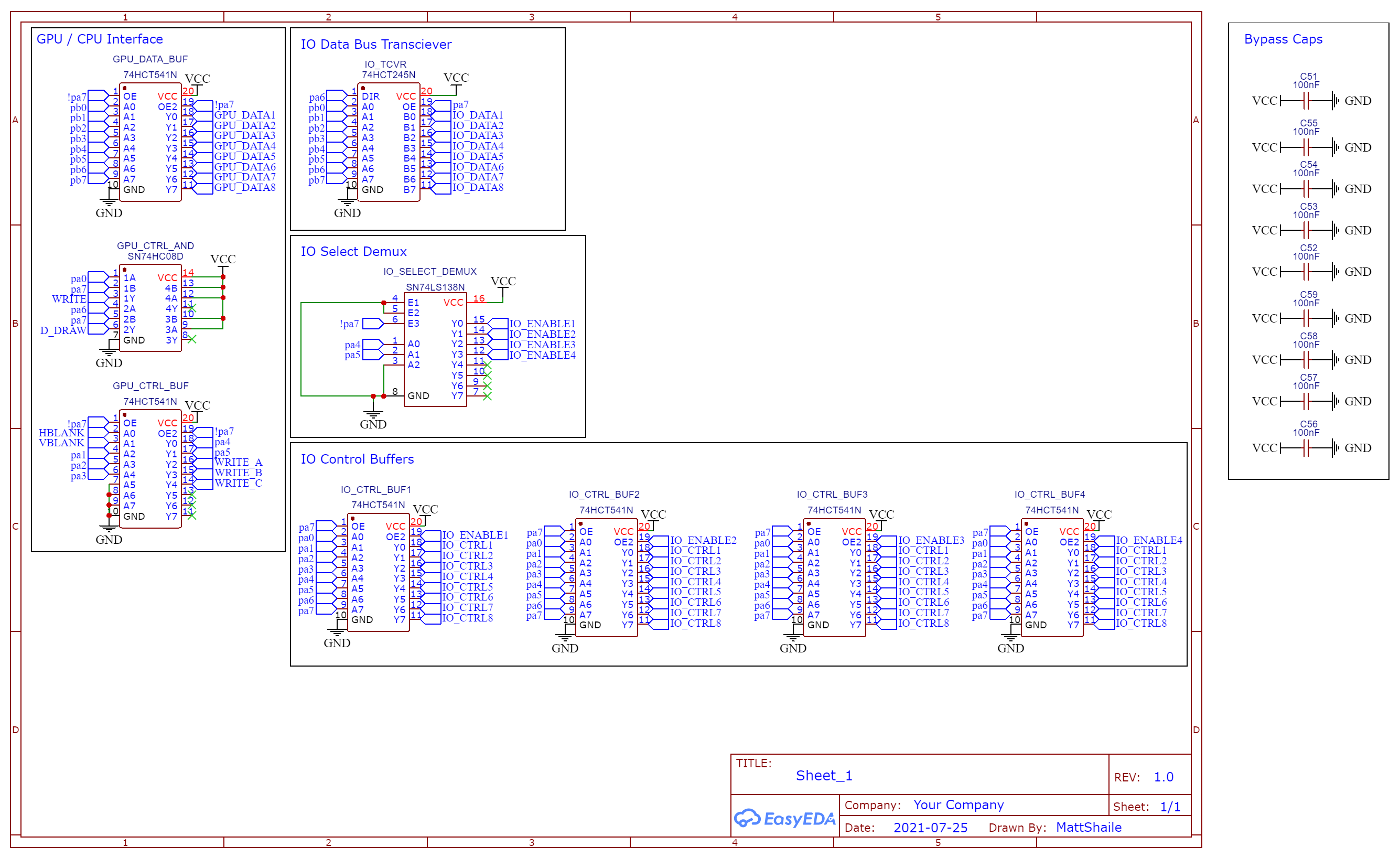
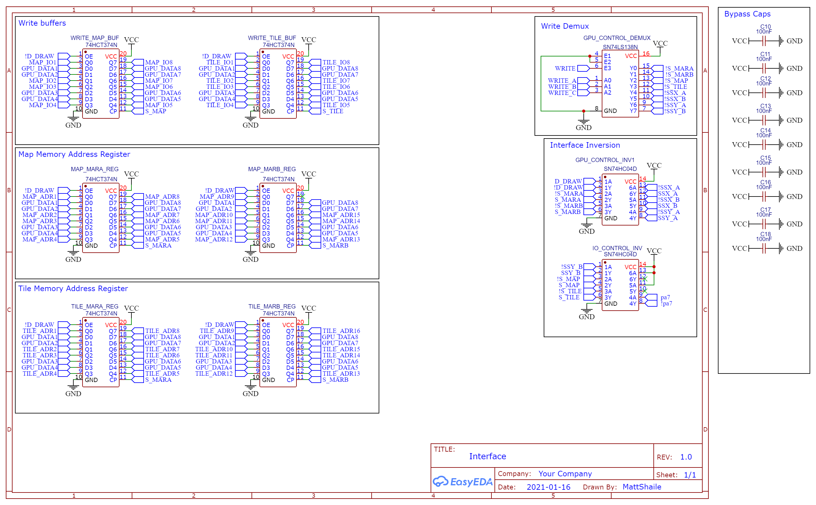
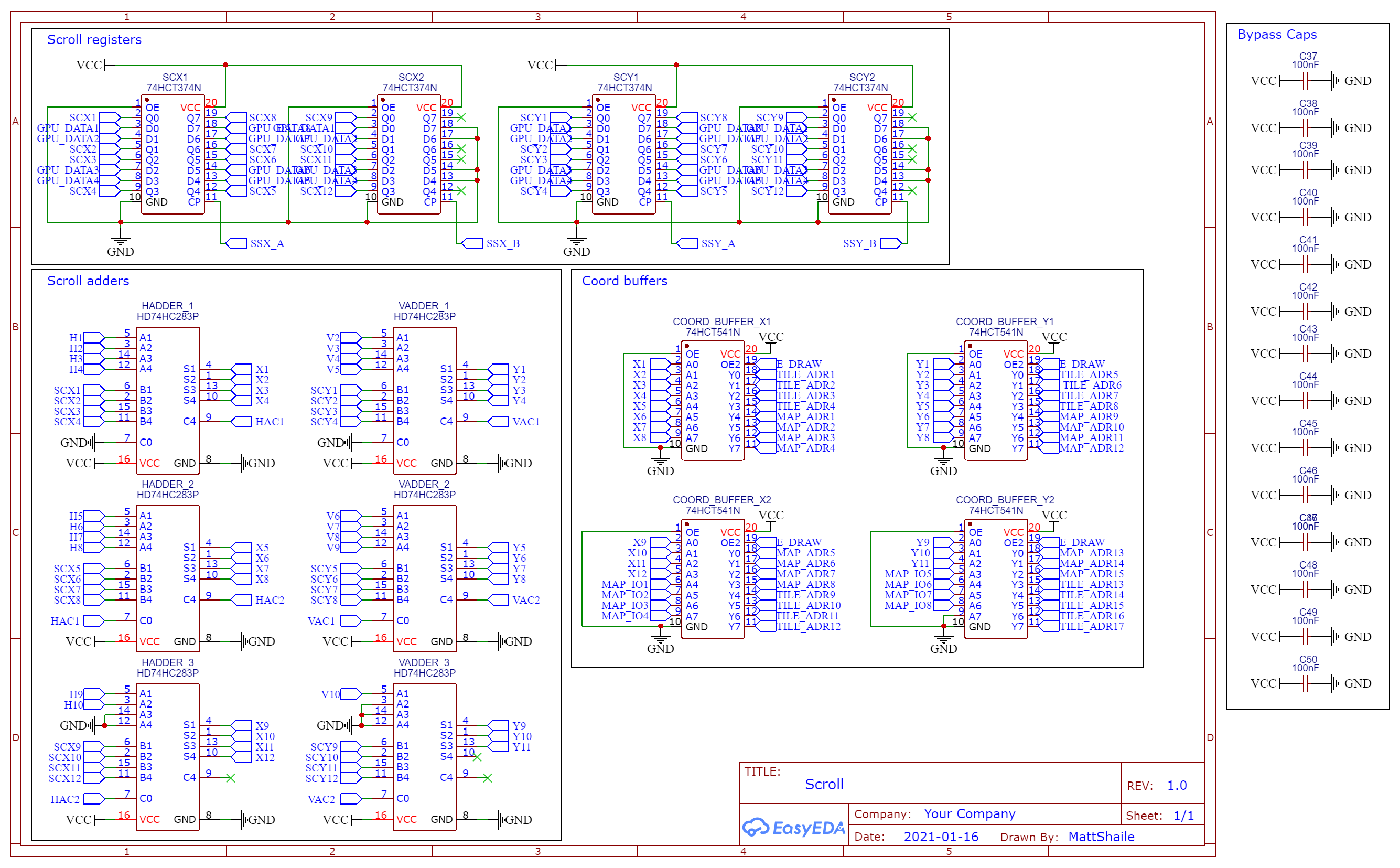
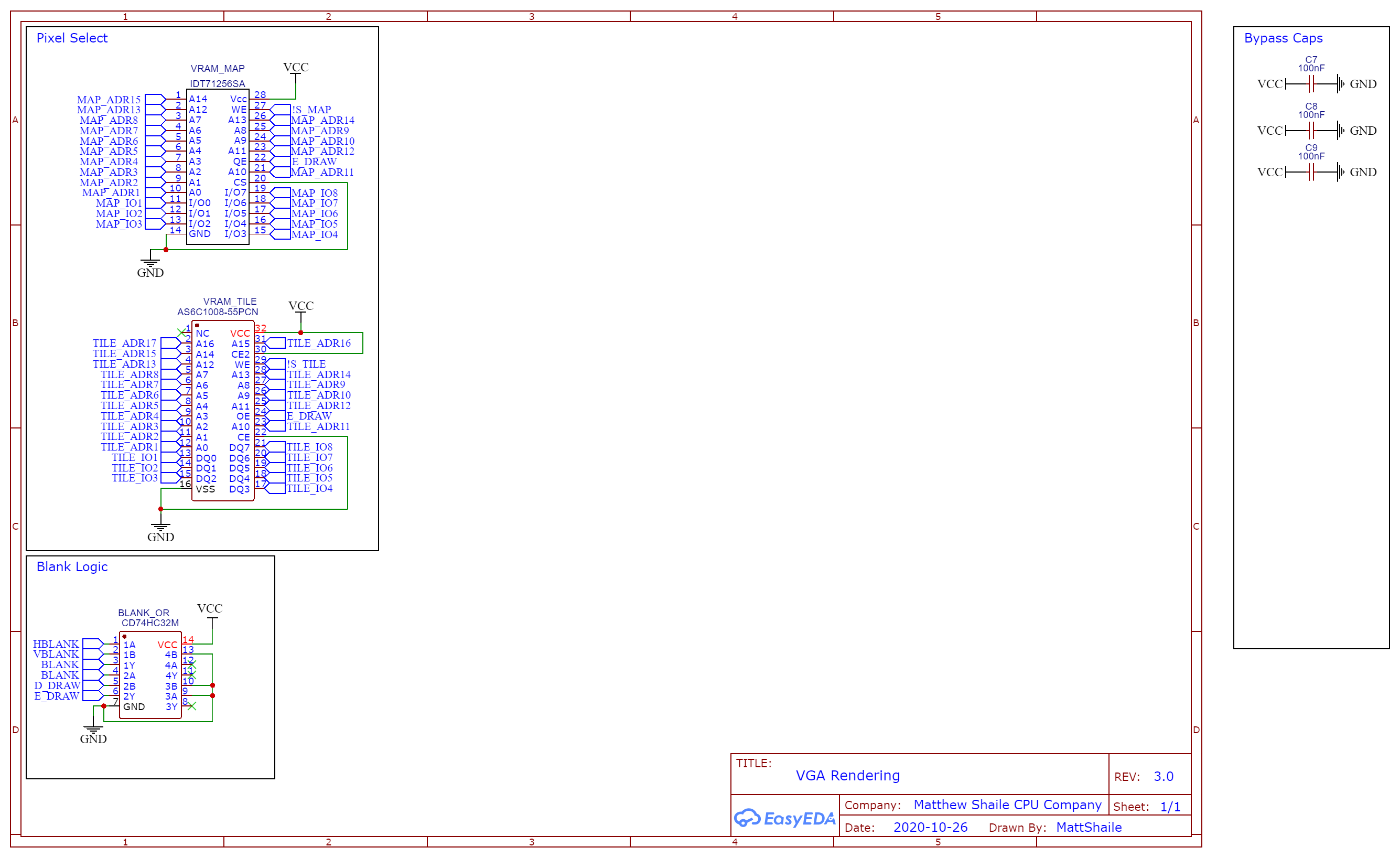
The schematics
These are the final schematic sheets, drawn in EasyEDA. Click any of them for the full-size version.
The end
And that's where I stopped. The whole project was about finding out whether I could build it: first a video card from logic chips, then a GPU, then a computer to drive it, and finally one that boots programs from cartridges and runs BASIC. Once it could do all that, I'd answered the question. I never had much interest in actually using it to write games or programs.
The one thing I'd have liked to add is input on the real hardware, like a keyboard or controller card. Both only ever existed in the emulator.
All of the source code, including the BIOS, the example cartridges, the emulator and the schematics, is on Bitbucket.